Brother MFC700C Pro fix error codes list
– Compatible Printer model: Brother MFC700C Pro
– Brother MFC700C Pro Error Codes with instructions guide:
- Code: 10
- Description: When the light source (fluorescent lamp) was OFF, no A/D reference values of CCD video signals could be detected since it is less than the lower limit.
- Causes: • Fluorescent lamp • Inverter PCB • Mirrors • Scanner frame ASSY • Main PCB
- Code: 13
- Description: When the light source (fluorescent lamp) was ON, the A/D reference values of CCD video signals were less than the lower limit.
- Causes:
- Code: 14
- Description: When the light source (fluorescent lamp) was ON, the A/D reference values of CCD video signals exceeded the upper limit.
- Causes:
- Code: 20
- Description: Head driver temperature error.
- Causes: • Print head unit • Main PCB
- Code: 21
- Description: No purge operation has started although commanded.
- Causes: • Main PCB
- Code: 22
- Description: A sequence of purge operation could not finish.
- Causes:
- Code: 23
- Description: Internal Centronics interface timeout.
- Causes: • Print head unit • Main PCB
- Code: 31
- Description: The carriage cannot travel to the right or left.
- Causes: Before checking the following components, check the carriage movement as described in (Note 1) given on the next page. • Carriage ASSY • Encoder strip (Any stains or scratches? Hooked correctly?) • Paper feed motor • Hook switch PCB • Main PCB • Power supply PCB • Flushing box • Purge unit • CR base ASSY • Ink empty sensor PCB
- Code: 32
- Description: After driven by the specified number of pulses, the carriage does not stop (since it cannot detect the left end of the travel).
- Causes:
- Code: 33
- Description: The carriage movement parameter exceeded the travel range during printing.
- Causes:
- Code: 34
- Description: When initialized, the carriage could not detect the right or left end of the travel range.
- Causes:
- Code: 35
- Description: The carriage cannot move by a shortest distance.
- Causes:
- Code: 36
- Description: The carriage cannot move by a short distance.
- Causes:
- Code: 37
- Description: The carriage cannot move at all.
- Causes:
- Code: 38
- Description: The carriage stop position is out of the travel range.
- Causes:
- Code: 3A
- Description: Sudden carriage stop during printing acceleration.
- Causes:
- Code: 3B
- Description: Sudden carriage stop during printing deceleration.
- Causes:
- Code: 3E
- Description: The carriage has overridden the travel range.
- Causes:
- Code: 41
- Description: When the power was applied, the head power feed signal stuck to High even after the head current shutdown sequence.
- Causes: • Main PCB • Power supply PCB
- Code: 42
- Description: Even after the head current shutdown sequence for head replacement, the head power feed signal stuck to High.
- Causes:
- Code: 43
- Description: The head drive voltage sticks to Low.
- Causes: • Print head unit • Main PCB • Power supply PCB
- Code: 46
- Description: The number of performed purge sequences has reached the limit.
- Causes: • Flushing box • Ink absorber • Main PCB
- Code: 47
- Description: ROM error.
- Causes: • Main PCB
- Code: 48
- Description: Internal RAM error
- Causes:
- Code: 49
- Description: PWM value of the black LED out of the specified range.
- Causes: • Ink empty sensor PCB • Hook switch PCB • Main PCB
- Code: 4A
- Description: Ink cartridge load error detected when the power was applied.
- Causes: • Ink cartridges (Were they loaded when the power was first applied after replacement of the main PCB?) • Main PCB • CR base ASSY
- Code: 4B
- Description: Abnormal carriage travel speed detected when the power was applied.
- Causes: • Encoder strip (Any stains or scratches? Hooked correctly?) • Purge unit • Flushing box • CR base ASSY • Carriage ASSY • Main PCB • Ink empty sensor PCB
- Code: 4C
- Description: Head voltage error.
- Causes: • Print head unit • Main PCB • Power supply PCB
- Code: 50
- Description: The purge cam HP switch does not come ON or go OFF even after the purge cam has been driven by the specified number of pulses.
- Causes: • Purge unit • Purge gear frame • CR base ASSY • Paper feed motor • 1st-bin sensor PCB • Main PCB
- Code: 51
- Description: The purge cam HP switch sticks to ON in the initialization sequence.
- Causes:
- Code: 52
- Description: At the time of purge operation, the carriage has not stopped in the purge position.
- Causes:
- Code: 53
- Description: The purge cam HP switch has come ON when the carriage was in the wipe position.
- Causes:
- Code: 54
- Description: Abnormal number of pulses required for a single rotation of the purge cam.
- Causes:
- Code: 70
- Description: Ink-empty mark error.
- Causes: • Ink empty sensor PCB • 1st-bin sensor PCB • 2nd-bin sensor PCB • 1st-bin registration sensor • 2nd-bin registration sensor • Main PCB
- Code: 73
- Description: No ink cartridge loaded.
- Causes: • Ink cartridge sensors • Main PCB • CR base ASSY
- Code: 74
- Description: All the four color inks have run out.
- Causes: • Operation procedure (Any wrong procedure?)
- Code: 79
- Description: Head thermister broken.
• Carriage ASSY • Main PCB - Causes:
- Code: 7A
- Description: The carriage encoder failed to detect a paper jam.
- Causes: • Encoder strip (Any stains or scratches? Hooked correctly?) • CR base ASSY
- Code: 7E
- Description: No print head mounted.
- Causes: • Print head unit • Main PCB • Carriage ASSY
- Code: 80
- Description: Recording paper size error.
- Causes: • Paper width sensor actuator • Main PCB • 1st-bin sensor PCB • 2nd-bin sensor PCB • 1st-bin registration sensor • 2nd-bin registration sensor
- Code: 82
- Description: Recording paper feeding error.
- Causes: • 1st bin • 2nd bin • 1st-bin sensor PCB • 2nd-bin sensor PCB • 1st-bin registration sensor • 2nd-bin registration sensor • Paper width sensor actuator • Main PCB
- Code: 83
- Description: Recording paper jam. (MFC7200FC: The 2nd-bin registration sensor sticks to OFF, indicating that paper has jammed. MFC7000FC/MFC Pro-700C: The 1st-bin registration sensor sticks to OFF, indicating that paper has jammed.)
- Causes: • 1st-bin sensor PCB • 2nd-bin sensor PCB • 1st-bin registration sensor • 2nd-bin registration sensor
- Code: 84
- Description: Recording paper jam. (The ink empty sensor detects a paper jam.)
- Causes:
- Code: 88
- Description: Recording paper jam (MFC7200FC: Even after the 2nd-bin registration sensor has come ON, the ink empty sensor does not detect paper. MFC7000FC/ MFC Pro-700C: Even after the 1st-bin registration sensor has come ON, the ink empty sensor does not detect paper.)
- Causes: • Paper width sensor actuator • Ink empty sensor PCB • 1st-bin sensor PCB • 2nd-bin sensor PCB • 1st-bin registration sensor • 2nd-bin registration sensor
- Code: A1
- Description: Top cover opened.
- Causes: • Cover sensor PCB • Main PCB
- Code: A2
- Description: Document too long to scan.
- Causes: • Document front sensor actuator • Document rear sensor actuator • Document sensor PCB • Cover sensor PCB • Document feed roller • Scanner motor • Main PCB
- Code: A3
- Description: Document not detected by the document rear sensor.
- Causes:
- Code: A4
- Description: 50% or more faulty of white level data.
- Causes: • Mirrors (Any stains or scratches?) • Cover glass (Any stains or scratches?) • Scanner frame ASSY • Main PCB

Solved Brother MFC700C Pro Error codes
- Code: A5
- Description: Faulty operation of DMA0 during scanning.
- Causes: • Main PCB
- Code: A6
- Description: Faulty operation of DMA1 during scanning.
- Causes:
- Code: A7
- Description: One-line feeding timeout.
- Causes:
- Code: A8
- Description: One-line scanning timeout.
- Causes:
- Code: AC
- Description: Less than 50% faulty of white level data.
- Causes: • Mirrors (Any stains or scratches?) • Cover glass (Any stains or scratches?) • Scanner frame ASSY • Main PCB
- Code: AD
- Description: 1st-bin’s or 2nd-bin’s front cover opened.
- Causes: • 1st bin cover sensor • 2nd bin cover sensor • Main PCB
- Code: E4
- Description: Out of recording paper.
- Causes: • 1st bin • 2nd bin • Paper width sensor actuator • 1st-bin registration sensor actuator • 2nd-bin registration sensor actuator • Document feed roller • Drive gear unit • Main PCB
- Code: E6
- Description: Write error in EPROM
- Causes: • Main PCB
- Code: F3
- Description: Voice message recording or playing-back not started.
- Causes: • Main PCB
- Code: F6
- Description: PC interface error
- Causes: • Interface cable • Main PCB • Centronics interface PCB
– Get more error code list with quick guide to fix printer product, click here
– About get help with reseting Epson inkpad or others, click here
About Canon Servie Tool V5610
– Canon Service Tool V5610 is a tool used to perform maintenance on Canon printers and reset Canon printers after replacement of parts such as replacing ink absorbents, print heads, printer mainboard, and others. Based on the many cases we have encountered, the Service Tool is most often used to reset ink absorber counter value when the waste ink absorber is full.
– The ink absorber is going to be full of box, it has to be replaced or cleaned the waste ink absorber. Also, replaceing or cleaning the waste ink absorber, you need to repair or reset the waste ink counter value, cause those parts are concerned to each others.
– So using Canon Service Tool V5610 to reset the waste ink counter value becomes effective when the ink absorber is replaced or cleaned.

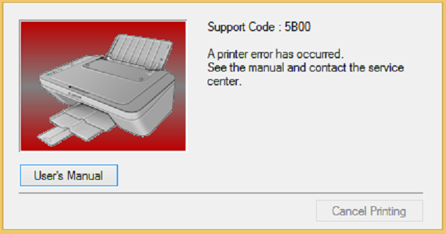
– Canon Service Tool V5610 can use to fix error code 5B00, 5B02, 5B04, 5B14, 1701, 1702, 1700 on your printer. You must enter Service Mode on your printer to use this Canon Service Tool.
– If the printer can not enter Service Mode, you can not reset it by Canon ST V5610. In this case, change EEPROM on the logic board.
Canon Service Tool V5610 Functions
– Fix Canon printer 7 times/ 8 times red light blinking:

– Fix Canon printer error code: 5B00, 5B01, 1700, 1701

Enter Service Mode on Canon Printer
1. Turn off a printer
2. Press and hold the Resume/Cancel/Stop button
3. Press and hold the ON button (do not release both buttons)
4. Release the Resume/Cancel/Stop button (do not release the ON button)
5. While holding the ON button, press the Resume/Cancel/Stop button 5 times, then release both the ON and Resume/Cancel/Stop buttons together.
– Canon printer in service mode: computer detects new hardware, led on printer goes green light.
For more information about Canon Serice Tool V5610
– Get more information about Epson XP 15000 troubleshooting, click here
– Buy cheap key of Epson WIC Reset Tool, CLICK HERE
– Key Epson Adjustment Program, CLICK HERE
https://dnasofts.com/download-epson-xp-6100-driver-firmware-and-manuals/
Contact us to get support with Brother MFC700C Pro Error case
Telegram: https://t.me/hyperaktiv
Facebook: https://www.facebook.com/dngnm/
Or click here to get more ways.
Source:
https://dnasofts.com
https://shop.nguyendangnam.com/

